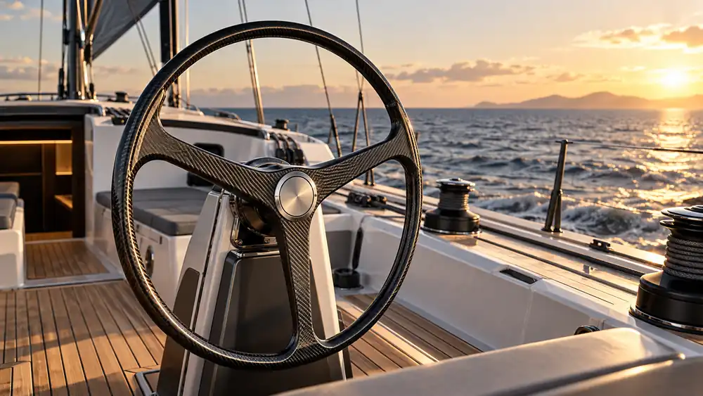
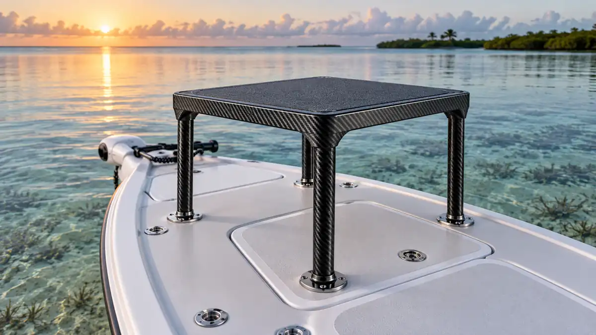
A carbon fiber boat hardtop can remove weight from one of the highest points on a vessel while creating a stiff platform for shade, lighting, antennas and electronics. That sounds straightforward, but a reliable hardtop is not simply a fiberglass roof remade with black fabric. Its laminate, core, hardpoints, supports, drainage and equipment interfaces must be engineered as one load-carrying system.
This guide explains the decisions that matter to boat builders, yacht designers and marine equipment brands. It covers structural inputs, sandwich construction, manufacturing routes, quality control and the information an OEM supplier needs before tooling begins. Noah Composites can provide custom OEM and ODM development for carbon fiber hardtops and related carbon fiber marine products, from design review and prototyping through repeat production.
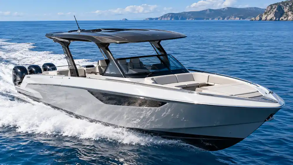
Engineering takeaway: The best carbon fiber boat hardtop is designed backward from vessel loads, equipment mass, support geometry and service conditions. Material selection comes after those inputs are defined.
Why hardtop weight matters more than the same weight below deck
Every kilogram added to a roof is positioned well above the vessel’s center of gravity. Reducing that elevated mass can support better roll behavior, acceleration and handling, although the actual effect must be evaluated for the complete vessel. It may also reduce the load carried by pillars, deck attachments and lifting equipment during assembly.
Carbon fiber has high specific stiffness, so a properly engineered shell can achieve the required rigidity with less mass than a comparable metal or conventional fiberglass structure. Stiffness is especially important because a hardtop must resist vibration, panel flutter and movement around windscreens, doors or electronics. The practical goal is not the thinnest possible laminate. It is a balanced structure that meets stiffness, strength, impact, fatigue and durability requirements with an appropriate safety margin.
| Decision factor | Carbon fiber sandwich | Fiberglass sandwich | Aluminum hardtop |
|---|---|---|---|
| Weight potential | Lowest when optimized | Moderate | Moderate and geometry-dependent |
| Stiffness per unit mass | Excellent | Good | Good |
| Corrosion behavior | Composite does not rust; metal interfaces need isolation | Composite does not rust | Requires alloy, coating and drainage control |
| Complex styling | Excellent molded freedom | Excellent molded freedom | More fabrication and joining constraints |
| Upfront tooling | Moderate to high | Moderate | Often lower for one-off fabrication |
| Best fit | Premium, performance and repeat OEM programs | Cost-sensitive production | One-offs and simpler fabricated forms |
Start with the load case instead of the laminate
A supplier cannot responsibly finalize a laminate from overall length and width alone. The engineering package should describe how the boat is used and how the roof is supported. Relevant inputs can include vessel speed, design category, maximum wind exposure, accelerations, green-water or slam exposure, support spacing and any requirement for a person to stand on the roof.
Permanent and operating loads
Radar arrays, satellite domes, outriggers, antennas, searchlights, solar panels, hatches and retractable mechanisms create concentrated loads. Their mass and center of gravity are only the beginning. Designers also need operating moments, fastener patterns, cable penetrations and maintenance access. A radar pedestal can produce a local bending problem even when the overall roof panel is adequately stiff.
Wind, inertia and vibration
The roof experiences aerodynamic pressure and suction as the boat moves, plus inertia from vessel acceleration and wave impacts. Unsupported spans can vibrate, and equipment may amplify fatigue at local interfaces. Modal or finite-element analysis can be useful for large, fast or heavily equipped hardtops, but the model is only as credible as its boundary conditions and material data.
Applicable standards and owner requirements
The final design basis depends on vessel type, market and classification requirements. The ISO 12215-5 framework addresses design pressures and structural determination for small craft, while ISO 12215-6 discusses structural arrangements and details. These references do not replace project-specific engineering, but they show why load transfer, local reinforcement, bonding and sandwich details must be documented.
A sandwich panel is more than carbon skins around foam
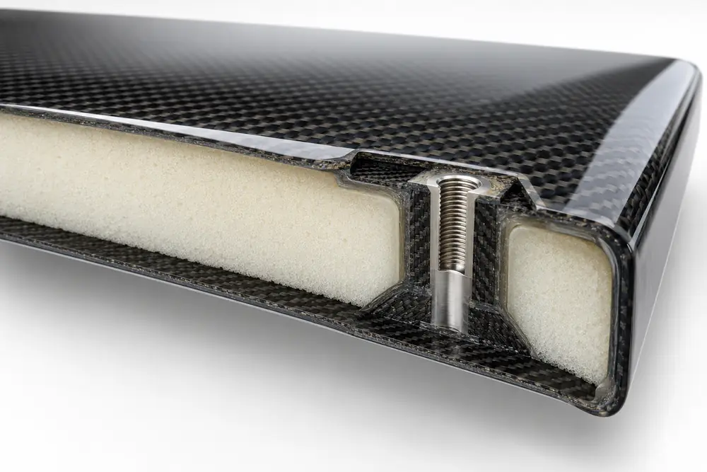
Most large hardtops are stiffness-driven. Separating two strong skins with a lightweight core increases bending rigidity without filling the section with solid laminate. The carbon skins carry in-plane tension and compression, while the core stabilizes them and transfers shear. Core thickness and density are therefore design variables rather than cosmetic choices.
Choose core by function and environment
PVC, PET and SAN structural foams are common candidates, with different density, temperature, toughness, resin-uptake and forming characteristics. Honeycomb may be suitable in selected high-performance areas but requires careful edge sealing and moisture management. Core choice must remain compatible with cure temperature and pressure. Gurit’s overview of marine production materials also highlights the role of lightweight cores in weight reduction and efficient composite production.
Hardpoints prevent crushed core and loose equipment
Bolting a radar or support bracket through ordinary foam can crush the core, relax preload and allow water entry. Higher-density inserts, potted regions or solid laminate pads should spread concentrated loads. Their geometry needs gradual transitions to avoid creating a new stress concentration at the edge of the reinforcement.
Edges and penetrations need sealing
Cut edges, drain openings, wire holes and fastener penetrations should not expose absorbent core. A robust detail removes or locally replaces the core, bonds the insert or potting compound, and seals the laminate before hardware installation. This is both a structural and durability requirement.
Metal hardware must be isolated from carbon
Carbon fiber is electrically conductive and relatively noble. In the presence of saltwater, direct contact with aluminum can accelerate galvanic corrosion of the aluminum. Stainless hardware can also create crevice and interface concerns. A marine carbon fiber hardtop therefore needs an isolation strategy, not merely sealant added during final assembly.
Depending on the joint, the design may use fiberglass isolation plies, nonconductive bushings, compatible primers, bedding compounds, sealed fasteners and controlled drainage. The isolation must continue around hole walls and edges—not only across the visible face. Hardware material, coating, torque and inspection access should be specified in the assembly drawing.
Integrate equipment before the first tool is cut
Late equipment changes are expensive because they can affect structure, appearance and tooling. The CAD model should reserve installation zones, cable paths, drainage slopes, service panels and bonding surfaces. Equipment should have defined envelopes for removal and replacement, not just enough room for initial installation.
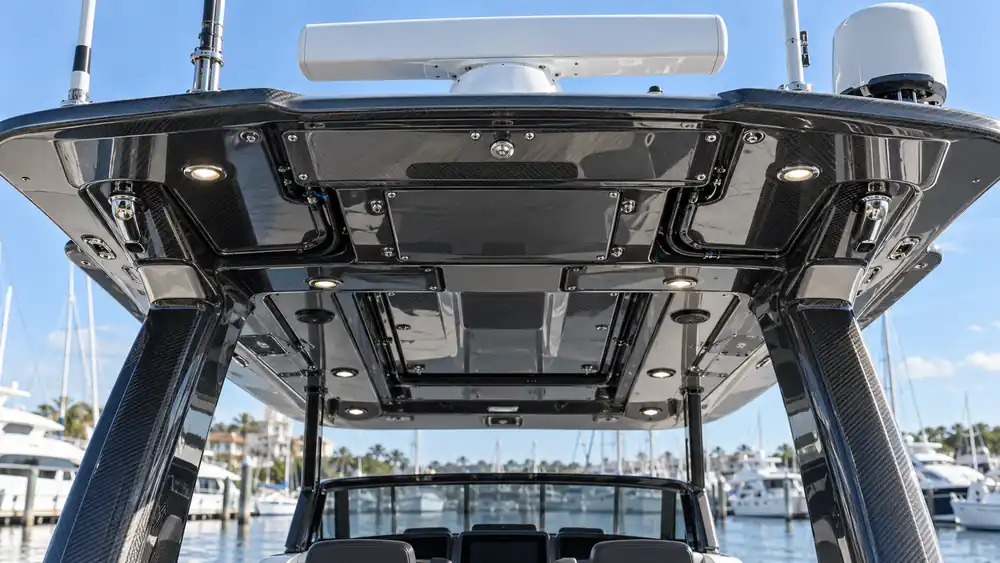
- Radar and antennas: define mass, bolt pattern, operating moment, cable bend radius and any radio-frequency transparency requirement.
- Lighting: provide heat management, drainage, connector access and replaceable mounting features.
- Solar panels: consider adhesive area, thermal expansion, cable routing and walk-on restrictions.
- Drainage: build in crown, channels and outlets so water does not pool around inserts or equipment.
- Retractable sections: validate hinge, actuator and latch loads across the full motion range.
Choosing the right manufacturing route
The production process should follow part size, geometry, surface requirements, structural targets, volume and tooling budget. A premium exposed-weave surface may favor female tooling and controlled prepreg placement. A large painted roof may allow a different process strategy while still meeting structural requirements.
Prepreg and autoclave curing
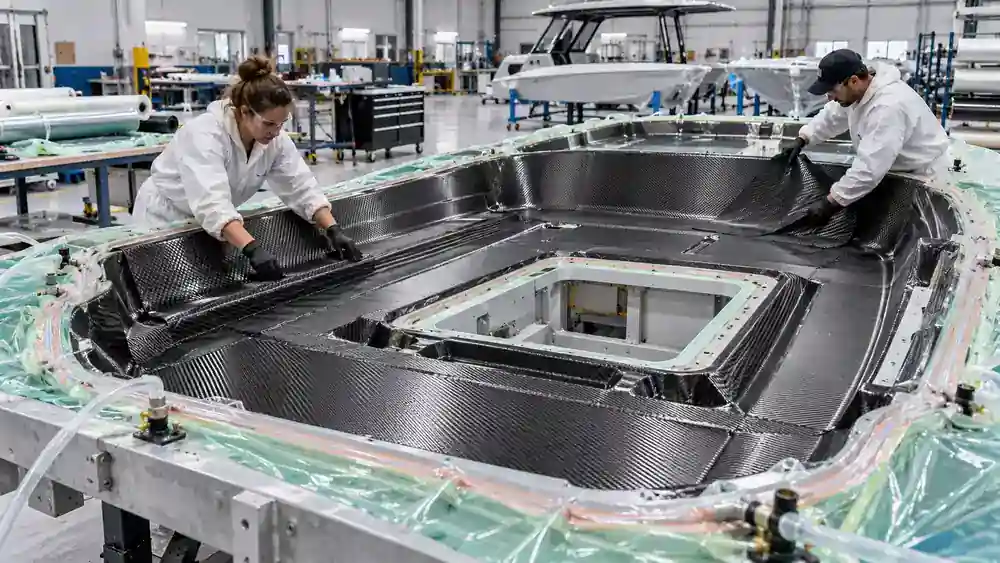
Prepreg offers controlled resin content and repeatable reinforcement placement. Autoclave pressure can improve consolidation and surface quality when the complete material and tooling system is designed for the cure cycle. CNC-cut ply kits and a controlled carbon fiber layup design help maintain fiber orientation and repeatability around compound curvature.
Vacuum infusion
Infusion can be attractive for large components and lower-cost reinforcement systems. The flow plan, permeability, resin viscosity, temperature and vacuum integrity must be validated so distant regions fill without dry fiber, excessive resin or trapped air. Cosmetic outer skins may need a dedicated surface strategy.
Matched-tool or compression approaches
For repeat programs and suitable geometries, closed tooling can support consistent thickness, integrated detail and faster cycles. Tooling investment is higher, so expected annual volume and design stability should be considered early. Noah Composites can evaluate prepreg/autoclave, vacuum-assisted and compression-based routes according to the hardtop geometry and program target rather than forcing every design into one process.
Finish requirements influence structure and cost
Exposed carbon demands careful fabric alignment, seam planning and surface control. Painted parts can hide weave transitions but still require stable substrates and compatible primers. In either case, the resin or coating system must protect the composite from ultraviolet exposure, moisture and cleaning chemicals.
Buyers should define acceptable weave distortion, pinholes, print-through, gloss range, color variation, repair limits and visible-zone boundaries. Without an agreed cosmetic standard, a structurally acceptable part can still fail incoming inspection. The article on carbon fiber defects and quality control explains how voids, wrinkles, delamination and surface issues relate to process control.
How to validate a carbon fiber boat hardtop
Inspection should be tied to design risk. A useful control plan separates raw-material traceability, in-process verification and final acceptance rather than relying only on a polished surface.
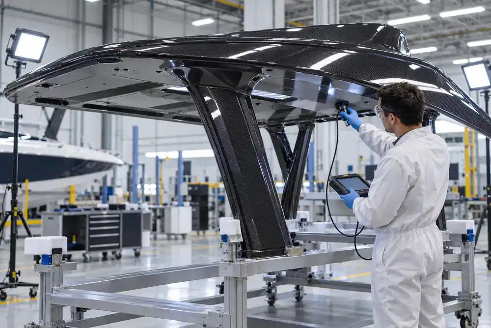
- Material control: verify fiber, resin, adhesive and core batches, storage history and shelf life.
- Tool and ply checks: confirm mold condition, release system, ply kit revision, orientation and insert location.
- Process records: retain vacuum checks, cure temperature, pressure and time data where applicable.
- Dimensional inspection: measure datums, support interfaces, equipment holes, edge profiles and overall twist. CNC finishing can improve repeatability; see Noah’s carbon fiber CNC machining capability.
- Bond and laminate inspection: use visual inspection, tap testing or suitable NDT for critical zones as defined by the engineering plan.
- Proof or functional testing: validate representative load cases, drainage, equipment fit and installation sequence on first articles.
What determines carbon fiber hardtop cost
There is no responsible universal price per square meter. Cost depends on geometry, laminate area, core machining, insert count, tooling, cure process, cosmetic grade, inspection, assembly and annual volume. A large simple painted shell can cost less to produce than a smaller exposed-weave part with numerous equipment recesses and tight visual standards.
The lowest quotation may omit engineering work, production tooling, fixtures, NDT, coating or packaging. Compare quotations against a shared scope. For repeat OEM programs, evaluate total installed cost, including fitting time, rejected parts, rework, hardware preparation and field warranty—not only molded-part price.
What to include in an OEM request for quotation
A complete RFQ reduces assumptions and makes supplier comparisons more meaningful. If some inputs are not yet available, identify them as open decisions instead of allowing each supplier to invent a different requirement.
- 3D CAD, 2D drawings, datum scheme and controlled revision;
- overall dimensions, target mass and allowable deflection;
- vessel type, speed, use profile and environmental exposure;
- support locations, deck interfaces and installation sequence;
- equipment list with mass, bolt pattern, loads and service envelopes;
- required standards, design factors and validation responsibility;
- surface zones, weave orientation, color, gloss and repair criteria;
- annual volume, prototype quantity, delivery schedule and packaging needs;
- inspection reports, material certificates and traceability requirements.
How Noah Composites supports custom hardtop programs
Noah Composites can OEM a carbon fiber boat hardtop for boat builders, yacht manufacturers and marine equipment brands. The collaboration can begin with customer CAD or a reference sample and proceed through design-for-manufacture review, tooling, prototype molding, CNC trimming, surface finishing, dimensional inspection and production.
The company’s integrated composite capabilities support automated material cutting, core machining, prepreg layup, autoclave curing, compression molding, CNC finishing, coating and inspection. This makes it possible to coordinate the shell, reinforcement, inserts and finish within one controlled manufacturing workflow. Learn more about the company’s engineering and quality organization on the About Noah Composites page.
Planning a new hardtop or replacing an existing fiberglass or metal design? Prepare the RFQ inputs above and contact Noah Composites for a project-specific process recommendation, prototype plan and OEM quotation.
Frequently asked questions
Is a carbon fiber boat hardtop always lighter than fiberglass?
It can be substantially lighter when both structures are optimized for the same loads and stiffness. Simply replacing fiberglass plies one-for-one with carbon may waste material or create an unbalanced design. The comparison should include skins, core, inserts, supports, hardware and finish.
Can radar and antennas mount directly to the carbon roof?
They should mount only at engineered hardpoints. The design must distribute fastener and operating loads, seal the core, manage cables and address any electromagnetic requirement. Local drilling into an ordinary foam-core region is not an acceptable substitute.
How do you prevent corrosion where the hardtop meets aluminum supports?
Use a documented isolation system such as fiberglass barrier plies, nonconductive bushings, compatible coatings and sealants, sealed hole walls and effective drainage. The correct stack depends on the metals, joint loads and service environment.
Is prepreg necessary for every custom marine hardtop?
No. Prepreg is valuable for resin control, performance and premium cosmetics, but infusion or another controlled process may be more appropriate for a large painted component or a different production target. Engineering requirements and total program economics should drive the selection.
What files does Noah Composites need to start an OEM review?
Useful starting inputs include 3D CAD, drawings, support geometry, equipment loads, target weight, finish expectations, quantity and required standards. If the design is incomplete, Noah Composites can identify missing manufacturing and interface information during the initial review.